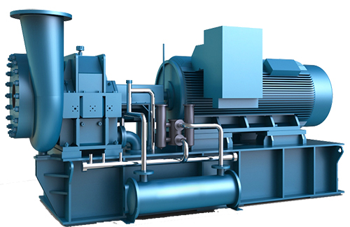


Centrifugal Blower Compressor
Hits:3556
Published Date:05-01-2004
Summary:
Type: Centrifugal Blower
Power Range: 75kW -9100kW
Pressure Range: 2.5bar - 45bar
Air Flow Range: 25 m3/min - 1500 m3/min
Cooling System: Air Cooling or Water Cooling
Power Source: AC Power 380V/3P/50HZ, can be customied.
Structure Type: Open Type
Trademark: SUCCESS ENGINE, OEM
Certificate: CE, UL, ASME, CCS
Min. Order: 1 piece
Warranty: One Year
Transport Package: Wooden box
Trade term: CIF, CFR, FOB, EX-WORKS
Previous: No message!
Next: Air Suspension Blower
Product Introduction:
|
SUCCESS ENGINE Centrifugal Compressor SUCCESS ENGINE is specializing in the field of civil impeller machinery, focusing on the two major requirements of “energy efficiency ratio" and "quality reliability", and has gathered domestic first-class engineer on aviation power, impeller machinery and suspension bearing. Using high-level advanced tools, software and equipment, through continuous self-development and innovation, it leads the civil impeller machinery industry to improve its innovation capabilities. SUCCESS ENGINE centrifugal compressor has large flow, with high efficiency and no oil discharge. It is high-speed impeller mechanical equipment customized according to the user's process requirements. |
|
 
|
|
|
Centrifugal Blower Compressor F.A.D: 40~1500 m3/min Working pressure: 0.8~10 bar. GDC series gear-driven centrifugal compressors, centrifugal blowers are widely used in various industries which have the requirement for large-flow and continuous operation. |
|
|
Aviation Design Concept - Impeller Using finite element analysis software of NASTRAN, ANSYS, Abaqus, etc., to carry out one-dimensional geometric and thermal design, two-dimensional flow design, three-dimensional blade design and strength check of impellers and blades. Through simulation, it can be judged whether the impeller design meets the design standards of aero-engine, and the service life of the impeller can be predicted. Create high-efficiency aviation-grade impellers with the best "power energy efficiency ratio". |
|

|
|
|
High-speed Tilting Pad Bearing Adopt horizontal split-type tilting-pad bearing which made by material of ISI 1040 carbon steel (inner) and babbitt alloy (surface), when the speed load changes, the bearing diagonal block is automatically centered, this automatic adjustment function can ensure the machine’s smooth operation. |
|

|
|
|
Aviation Standard High Speed Gearbox Horizontal split gearbox structure is used with aviation standard processing, manufacturing, debugging and inspection, with built-in high-speed forged alloy steel precision helical gears, the horizontal center divides the cylinder into upper and lower halves and connect by bolts, modular structure design is convenient for maintenance and repair. |
|

|
|
|
High Efficiency Removable Cooler and Air Intake Adjustment The cooler is separated from the gearbox, and the lubrication system is perfectly separated from the compressed air, ensuring that the compressed air is 100% clean and oil-free. Removable cooler, tube bundles is precisely matched with the finished shell, which can effectively improve the heat exchange rate between compressed air and water and reduce the consumption of cooling water. By adjusting the installation angle of inlet guide vane of the impeller, the pre-rotation of airflow can be adjusted within a range of 70-105%. |
|

|
|
|
Impeller Dynamic Balance Test Using advanced dynamic balance testing equipment, according to the requirements of "Dynamic Balance Test Procedure", a strict dynamic balance testing is carried out on each impeller and shaft assembly to ensure the balance and stability during high-speed operation. |
|

|
|
|
Advanced Large Screen PLC Monitoring System The control system includes a PLC controller and various sensors, and also with its own low-voltage control cabinet. Including but not limited to the following protection and control functions: auxiliary oil pump on/off, compressor on/off, emergency stop; Indicator light: auxiliary oil pump running, compressor ready to start, main motor running & alarm, etc.; Instruments: current, pressure, oil pressure and other monitoring instruments; Display the compressor operating parameters; Monitor the compressor operation and automatically alarm and shut down; The exhaust flow and pressure can be set and adjusted by users. The system predicts surge through differential pressure change, and realizes flow regulation by controlling the inlet guide vane and bypass valve, automatically tracks the change of surge line, adjusts surge control points, and ensures safe and reliable operation from low load to full load. Automatically check the compressor startup conditions; Monitor the components requiring maintenance, and have sensor self-inspection function; With Manual, single, local and remote (central control room) control switching function; With RS485 communication interface, it can not only monitor the compressor operation independently, but also can upload the relevant monitoring data to the user monitoring center through the LAN network to achieve real-time information feedback; The unit provides up to 31 display items, 13 alarm control items and 12 shutdown control items. |
|

|
|
|
Strict Production and Manufacturing Process Design, manufacture and assembly follow strict aviation standards and military nuclear quality assurance program requirements to effectively ensure the quality and operational reliability of equipment. |
|

|
|
| Test Evaluation and Analysis | |

|
|
| Production Circulation Area | |
|
|
|
| User Installation Scenario | |

|
|
| SUCCESS ENGINE Production Workshop | |

|
|
| Factory Environment | |

|
|


| Model |
Power kW |
Pressure Bar |
Air Flow m3/min |
Weight KG |
Dimension L*W*H mm |
| GDC-30 | 130-270 | 2.5-10 | 25-50 | 4200 | 2750*1460*2000 |
| GDC-60 | 260-450 | 2.5-11 | 48-85 | 4500 | 2850*1560*2000 |
| GDC-90 | 430-800 | 2.0-12 | 78-140 | 4900 | 2950*1660*2100 |
| GDC-120 | 710-1050 | 2.0-14 | 132-200 | 8100 | 3000*1660*2120 |
| GDC-150 | 980-1500 | 2.0-16 | 180-270 | 12000 | 4800*2200*2600 |
| GDC-250 | 1500-1900 | 2.0-18 | 270-360 | 18000 | 5300*2600*3000 |
| GDC-400 | 1960-2900 | 2.0-19 | 360-530 | 28000 | 5800*3000*3200 |
| GDC-650 | 2600-4900 | 2.0-35 | 470-890 | 48000 | 6200*3500*3800 |
| GDC-1200 | 4500-9100 | 2.0-45 | 830-1500 | 53000 | 7200*5000*4800 |
|
The volumetric flow parameter is the maximum volumetric flow that this compressor can generate under the specified working conditions (JB/T6430 standard requirements: suction absolute pressure 0.1MPa/suction temperature 20 ℃/suction relative humidity 0). Specifications are subject to change by SUCCESS ENGINE without notice and the detailed information is subject to Pre-sales consulting. |
|||||
|
Eamil us for detailed quotation: sales@segroup.ltd |

 Shanghai, China
 +86-13918322093

 www.segroup.ltd


 secompressor